A digital tachometer is an electronic device used to measure the rotational speed of a motor, fan, or any rotating object. It displays the value in revolutions per minute (RPM), making it a valuable tool in electronics projects, mechanical testing, and DIY automation.
In this project, we’ll learn how to build a DIY Digital Tachometer using Arduino and an IR sensor module. The IR sensor detects the rotation of a marked disc or motor shaft, while the Arduino processes the signal and calculates the RPM. Finally, the output can be displayed on a 16×2 LCD screen or OLED display for real-time monitoring.
This project is beginner-friendly, low-cost, and a great way to explore sensors, Arduino programming, and measurement systems.

What is a Digital Tachometer?
A digital tachometer is an electronic measuring device that detects the rotational speed of a shaft or disc and presents the result on a digital display. It usually employs sensors such as IR sensors, Hall effect sensors, or laser sensors to capture the motion.
In this project, we use an IR sensor with Arduino. The sensor generates pulses as a reflective strip on the rotating object passes in front of it. Arduino counts these pulses and converts them into RPM values using simple mathematical formulas.
Types of Tachometers (Contact vs. Non-Contact)
Tachometers can be broadly classified into two main types:
- Contact Tachometer
- Requires direct physical contact with the rotating object.
- Often uses a mechanical probe or wheel that touches the shaft.
- Suitable for low-speed applications but not ideal for delicate or high-speed systems.
- Non-Contact Tachometer
- Works without touching the rotating object.
- Uses infrared, laser, or optical sensors to detect speed.
- Safer, more accurate, and widely used in modern projects and industries.
Why Use Arduino for Building a Tachometer?
Arduino is one of the most popular choices for building a DIY tachometer because of:
- Ease of Use: Arduino IDE is beginner-friendly, and coding for pulse counting is simple.
- Low Cost: Both Arduino boards and IR sensors are inexpensive, making this project budget-friendly.
- Accuracy: Arduino can handle precise pulse counting and timing calculations.
- Flexibility: You can display results on an LCD, OLED, or even send them to a computer or smartphone.
- Learning Value: Building this project helps beginners understand sensors, interrupts, and real-time calculations.
By using Arduino, even beginners can design a professional-quality tachometer at home.
Circuit Schematic

Components Required
- Arduino Board (Uno/Nano)
- IR Sensor Module
- 16×2 LCD Display (with I2C module for easy wiring)
- Resistors and Wires
- Breadboard or PCB
- Power Supply (5V USB or Battery)
Circuit Diagram Explanation
To build a Digital Tachometer using Arduino and IR Sensor, you need to connect all components properly so that the sensor can detect motor speed and the Arduino can display RPM values on the LCD. The circuit is simple and beginner-friendly, making it an ideal project for DIY electronics learners.
Arduino to IR Sensor Connection
The IR sensor module has three pins: VCC, GND, and OUT.
- VCC → 5V on Arduino
- GND → GND on Arduino
- OUT → Digital Pin (D2 recommended)
Working logic: When the rotating object with a reflective strip passes in front of the IR sensor, it generates a digital HIGH pulse. Arduino detects these pulses and counts them to calculate RPM.
Using pin D2 or D3 is recommended because these pins support external interrupts, which provide more accurate pulse counting.
Arduino to LCD Connection
For displaying the RPM, a 16×2 LCD is commonly used. If you use an I2C module with the LCD, the wiring becomes much easier (only 4 wires).
With I2C Module (Recommended):
- VCC → 5V on Arduino
- GND → GND on Arduino
- SDA → A4 on Arduino Uno
- SCL → A5 on Arduino Uno
Without I2C Module: (requires more pins)
- RS → D7
- E → D6
- D4 → D5
- D5 → D4
- D6 → D3
- D7 → D2
- VCC → 5V
- GND → GND
Using I2C reduces wiring complexity and saves Arduino pins for other sensors.
Power Supply Setup
The project can be powered in multiple ways:
- USB Power (5V from Computer or Adapter) – Best for prototyping.
- External 9V Battery – Connect to Arduino’s VIN and GND pins.
- 5V Regulated Power Supply – For stable long-term operation.
Important Notes:
- Make sure the IR sensor receives 5V stable power; otherwise, it may give false readings.
- If using a motor as the rotating object, use a separate power supply for the motor to avoid electrical noise affecting the sensor.
Working of Arduino Tachometer
The Arduino-based tachometer works by detecting the rotation of an object and converting it into pulses per second, which are then calculated as RPM (Revolutions Per Minute). The IR sensor module acts as the “eye” of the system, while Arduino processes the signals and finally shows the result on an LCD screen.
How the IR Sensor Detects Rotation?
The IR sensor module has two main parts:
- IR LED (transmitter): continuously emits invisible infrared light.
- Photodiode (receiver): detects reflected IR light.
When a rotating object (like a motor shaft or disc) is fitted with a white reflective strip, the following happens:
- Each time the strip passes in front of the IR sensor, the light reflects strongly back to the photodiode.
- The IR sensor sends a digital HIGH pulse to the Arduino.
- When no strip is detected, the signal remains LOW.
This creates a sequence of pulses, where 1 pulse = 1 rotation (if one strip is used). Arduino counts these pulses in real time to calculate RPM.
RPM Calculation Formula
The basic formula for calculating RPM is:

Explanation:
- Number of Pulses in One Second → Arduino counts how many times the strip passes the sensor in one second.
- × 60 → Converts seconds into minutes.
- ÷ Number of Strips → If you use more than one reflective strip, Arduino divides accordingly. For example:
- 1 strip = 1 pulse per rotation.
- 2 strips = 2 pulses per rotation (so RPM must be halved).
This ensures accurate speed measurement even if multiple strips are used.
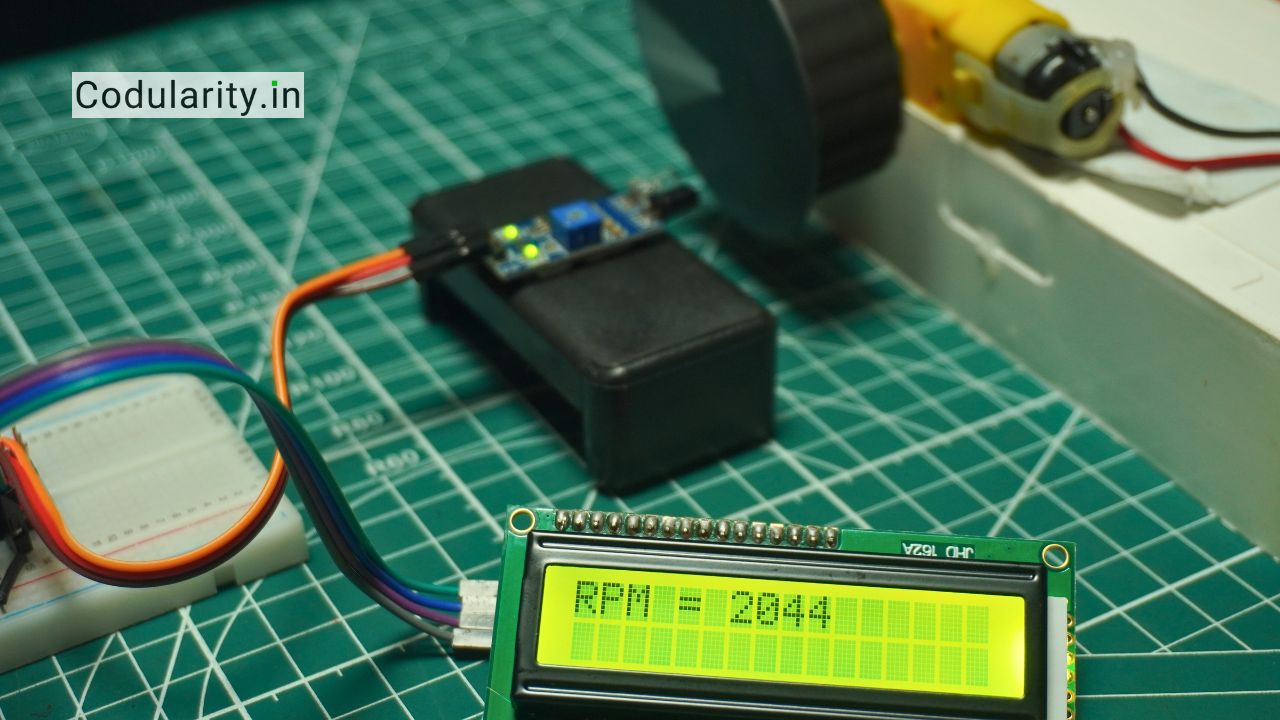
Displaying Results on LCD
Once the RPM value is calculated, Arduino sends the result to a 16×2 LCD display (or OLED).
- The LiquidCrystal_I2C library (for I2C LCDs) is commonly used for easy printing.
- Example display format:
Motor Speed:
1200 RPM- The display updates every second, providing a real-time speed measurement.
This makes the tachometer not only functional but also user-friendly. You can quickly see the motor’s performance without needing extra software or tools.
Source Code
The Arduino sketch for this project is simple: it counts the number of pulses received from the IR sensor, converts them into RPM values, and then displays the result on an LCD screen.
Here’s a sample code you can use:
/*
  Digital Tachometer using Arduino and IR Sensor
  Display: 16x2 LCD (with option for I2C or Non-I2C)
  Author: Codularity
*/

// ---------------- LCD SELECTION ----------------
// Uncomment the one you want to use:

#define USE_I2C_LCD     // Comment this line if using non-I2C LCD
//#define USE_NORMAL_LCD  // Uncomment if using direct pin LCD

// ---------------- INCLUDE LIBRARIES ----------------
#ifdef USE_I2C_LCD
#include <Wire.h>
#include <LiquidCrystal_I2C.h>
LiquidCrystal_I2C lcd(0x27, 16, 2);  // (I2C address, cols, rows) – change 0x27 to 0x3F if needed
#endif

#ifdef USE_NORMAL_LCD
#include <LiquidCrystal.h>
// Pins: RS, E, D4, D5, D6, D7 (adjust if wired differently)
LiquidCrystal lcd(7, 6, 5, 4, 3, 8);
#endif

// ---------------- SENSOR & VARIABLES ----------------
const int sensorPin = 2;   // IR sensor OUT pin connected to D2
volatile int pulseCount = 0;
unsigned long oldTime = 0;
int rpm = 0;

// ---------------- SETUP ----------------
void setup() {
  // Initialize LCD
  #ifdef USE_I2C_LCD
    lcd.init();
    lcd.backlight();
  #endif

  #ifdef USE_NORMAL_LCD
    lcd.begin(16, 2);
  #endif

  // Startup message
  lcd.setCursor(0, 0);
  lcd.print("Made by");
  lcd.setCursor(0, 1);
  lcd.print("Codularity");
  delay(2000);   // Show for 2 seconds
  lcd.clear();

  // Setup IR sensor input
  pinMode(sensorPin, INPUT);

  // Attach interrupt on sensor pin (D2) for pulse counting
  attachInterrupt(digitalPinToInterrupt(sensorPin), countPulse, RISING);
}

// ---------------- MAIN LOOP ----------------
void loop() {
  unsigned long currentTime = millis();

  // Calculate RPM every 1 second
  if (currentTime - oldTime >= 1000) {
    detachInterrupt(digitalPinToInterrupt(sensorPin));  // Stop counting temporarily

    // RPM formula: Pulses per second * 60 (for 1 reflective strip)
    rpm = pulseCount * 60;

    pulseCount = 0;          // Reset counter
    oldTime = currentTime;   // Reset timer

    // Display RPM on LCD
    lcd.clear();
    lcd.setCursor(0, 0);
    lcd.print("Motor Speed:");
    lcd.setCursor(0, 1);
    lcd.print(rpm);
    lcd.print(" RPM");

    attachInterrupt(digitalPinToInterrupt(sensorPin), countPulse, RISING);  // Resume counting
  }
}

// ---------------- INTERRUPT FUNCTION ----------------
void countPulse() {
  pulseCount++;
}Code Explanation (IR sensor pulse counting & timing)
- Library Setup:
LiquidCrystal_I2C.his used to communicate with the LCD.
- Sensor & Variables:
sensorPin = 2→ IR sensor is connected to Arduino pin D2.pulseCount→ Keeps track of how many times the reflective strip passes the sensor.oldTime¤tTime→ Used to measure time intervals (1 second).
- Interrupt Handling:
attachInterrupt()is used on pin D2, so every time the IR sensor outputs a pulse, the functioncountPulse()is triggered.- This ensures accurate pulse counting even at high speeds.
- RPM Calculation:
- Every 1 second, the Arduino calculates RPM as
pulseCount × 60. - If you use more than one reflective strip, divide by the number of strips.
- Every 1 second, the Arduino calculates RPM as
How RPM is Calculated in Code?
The line:
rpm = (pulseCount * 60);follows the formula:

- If 1 strip is used → RPM = pulses × 60
- If 2 strips are used → RPM = (pulses × 60) ÷ 2
This ensures accurate results no matter how many reflective strips are on the disc.
Common Errors and Fixes
- LCD Not Displaying Anything
- Check the I2C address of your LCD (commonly
0x27or0x3F). - Use an I2C scanner sketch to confirm the address.
- Check the I2C address of your LCD (commonly
- RPM Always Showing Zero
- Ensure the IR sensor OUT pin is connected to pin D2 (or D3) which supports interrupts.
- Make sure the reflective strip is bright white for proper detection.
- Unstable or Fluctuating Readings
- Use a black background + white strip for better contrast.
- Add a small capacitor (100nF) near the IR sensor for noise filtering.
- Keep the sensor at an optimal distance (2–5 cm) from the rotating object.
- Wrong RPM Value
- Check if you used more than one reflective strip and adjust the formula in code accordingly.
Applications of Digital Tachometer
A digital tachometer using Arduino and IR sensor has a wide range of real-world applications. Since it provides accurate and real-time RPM measurements, it is useful in robotics, industries, automotive systems, and hobby projects. Below are some common use cases:
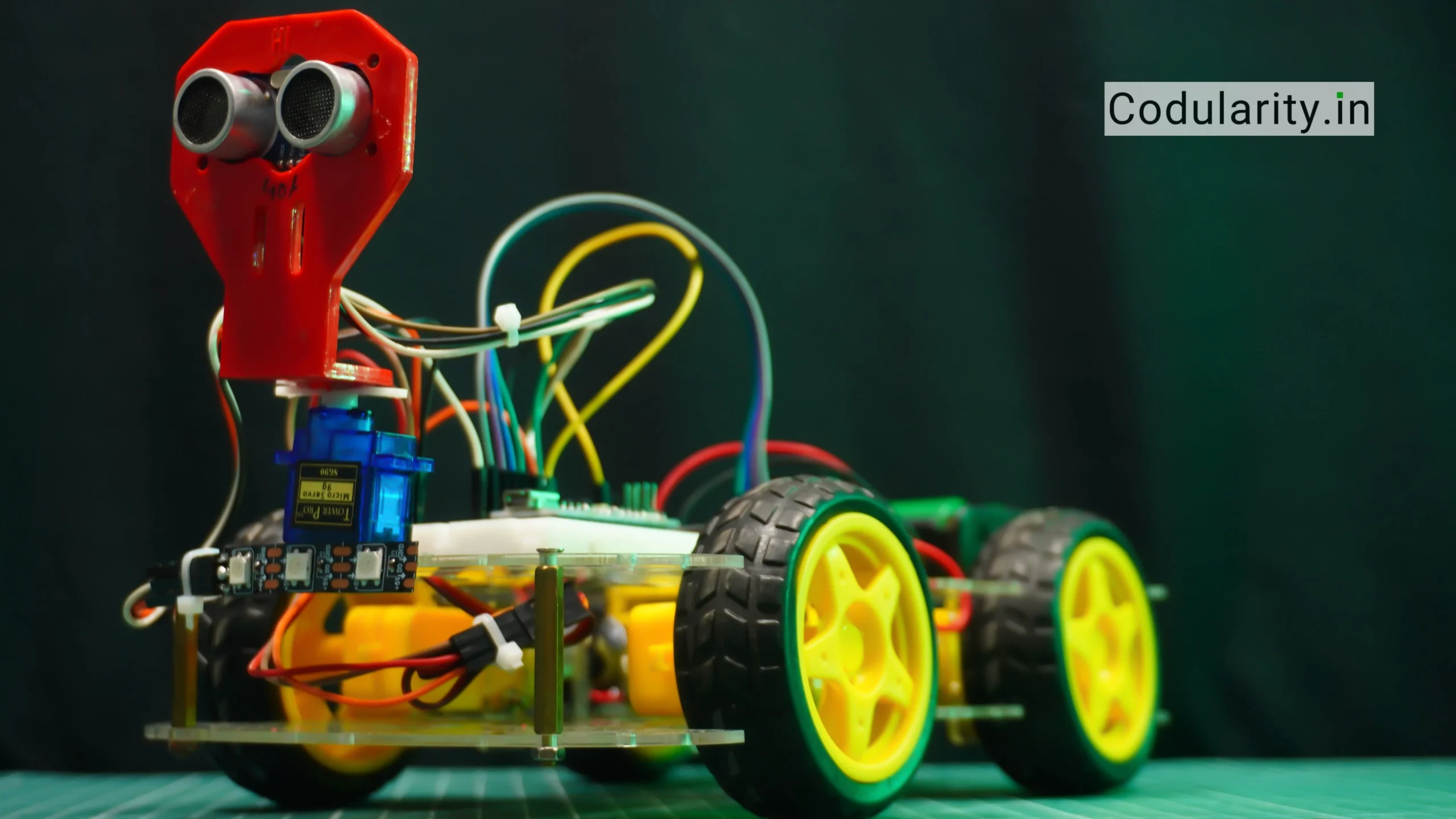
Measuring Motor Speed in Robotics
In robotics, controlling and monitoring motor speed is crucial.
- A digital tachometer helps measure the RPM of DC motors, stepper motors, or brushless motors.
- It ensures precise speed control for robotic arms, mobile robots, and conveyor systems.
- Feedback from the tachometer can be used in PID control loops to maintain a constant speed, even under varying loads.
This makes the Arduino-based tachometer an excellent tool for both learning and practical robotic applications.
Industrial Machine Speed Monitoring
In industries, machines like drilling machines, lathes, fans, and turbines must operate within a safe speed range.
- A digital tachometer can be attached to rotating shafts to continuously monitor RPM.
- If the speed goes beyond a limit, the system can trigger an alarm or shutdown mechanism to prevent damage.
- Compared to costly commercial tachometers, the Arduino version provides a low-cost yet reliable monitoring solution.
Thus, it is widely used for maintenance, testing, and preventive monitoring in workshops and factories.
Automotive and DIY Electronics Projects
In the automotive sector and DIY hobby projects, tachometers are equally important:
- Used in cars and bikes to measure engine RPM for performance testing.
- Helpful in designing RC cars, drones, and DIY electric vehicles where motor speed needs to be monitored.
- Great for DIY electronics learners, as it demonstrates how sensors and Arduino work together to create a real measurement system.
Hobbyists can also upgrade the tachometer with features like Bluetooth/Wi-Fi monitoring and mobile app displays.
Advantages of Arduino-Based Tachometer
Building a digital tachometer using Arduino and an IR sensor offers several benefits compared to traditional tachometers or expensive commercial instruments. It is cost-effective, accurate, and customizable, making it a perfect choice for students, hobbyists, and even small-scale industrial monitoring.
Low Cost and DIY Friendly
- The components required for this project—Arduino, IR sensor, and LCD—are inexpensive and easily available.
- Unlike industrial tachometers that can cost hundreds of dollars, this DIY version can be built for just a fraction of the cost.
- It is also easy to assemble and code, making it beginner-friendly for electronics learners and hobbyists.
Accurate RPM Measurement
- The use of an IR sensor with interrupt-based counting ensures reliable detection of rotations.
- By applying simple math formulas, the Arduino can calculate RPM with good precision.
- Non-contact measurement makes it safer and more accurate, especially for high-speed motors where mechanical tachometers may fail.
Easy to Upgrade with OLED/Serial Monitor
- The project is highly flexible and scalable.
- Instead of a basic 16×2 LCD, you can upgrade to a 128×64 OLED display for a modern look and clearer RPM readings.
- Data can also be sent to the Arduino Serial Monitor, or even logged into a computer or SD card for analysis.
- With additional modules like Bluetooth or Wi-Fi (ESP8266/ESP32), the tachometer can be connected to a mobile app or cloud dashboard.
Future Enhancements
The Arduino-based digital tachometer is simple and effective, but it can be further enhanced with advanced features. By adding wireless connectivity, mobile apps, or different types of sensors, this project can be transformed into a professional-grade instrument suitable for more demanding applications.
Wireless Tachometer using Bluetooth/Wi-Fi
- By adding a Bluetooth module (HC-05) or Wi-Fi module (ESP8266/ESP32), the tachometer can transmit RPM readings wirelessly.
- This allows real-time speed monitoring on a smartphone or computer without needing a wired LCD connection.
- Useful in remote monitoring applications, such as tracking motor performance in machines located far away.
Mobile App Integration
- The tachometer can be linked with an Android or iOS mobile app to display RPM data in a user-friendly format.
- Features like graph plotting, speed logging, and alerts can be added to make the system smarter.
- Apps can also be used to control motor speed if paired with a motor driver, creating a complete monitoring + control system.
Using Laser Sensor for Higher Accuracy
- Instead of a basic IR sensor, a laser sensor can be used for more precise detection.
- Laser tachometers are highly accurate and can measure very high RPMs where IR sensors may struggle.
- This upgrade makes the project suitable for professional laboratories, automotive testing, and high-speed industrial machines.
FAQs – Digital Tachometer Using Arduino and IR Sensor
1. What is a digital tachometer and how does it work?
A digital tachometer is a device that measures the rotational speed of a motor or shaft and displays the result in Revolutions Per Minute (RPM). In this Arduino project, an IR sensor detects pulses from a reflective strip, and Arduino converts them into RPM values, which are shown on an LCD.
2. Can I use any type of motor with this Arduino tachometer?
Yes, you can measure the speed of DC motors, stepper motors, brushless motors, or even fans. Just attach a reflective strip to the rotating part so the IR sensor can detect it.
3. How accurate is an Arduino-based digital tachometer?
The accuracy is quite good for DIY projects, typically within ±2% to ±5% depending on the quality of the IR sensor and reflective strip. For higher accuracy, a laser sensor can be used instead of an IR sensor.
4. Do I need an LCD to display RPM readings?
No, the LCD is optional. If you don’t have one, you can simply display the RPM values on the Arduino Serial Monitor. However, using an LCD or OLED display makes the project more user-friendly.
5. Can this tachometer be upgraded for wireless monitoring?
Yes. By adding modules like Bluetooth (HC-05) or Wi-Fi (ESP8266/ESP32), you can send RPM readings to a smartphone app or computer. This makes it suitable for remote monitoring and IoT applications.
Conclusion
Building a Digital Tachometer using Arduino and IR Sensor is a simple yet powerful project for electronics enthusiasts. It combines sensors, microcontrollers, and displays to create a useful measuring tool that can be applied in real-world scenarios like robotics, automotive testing, and industrial monitoring.