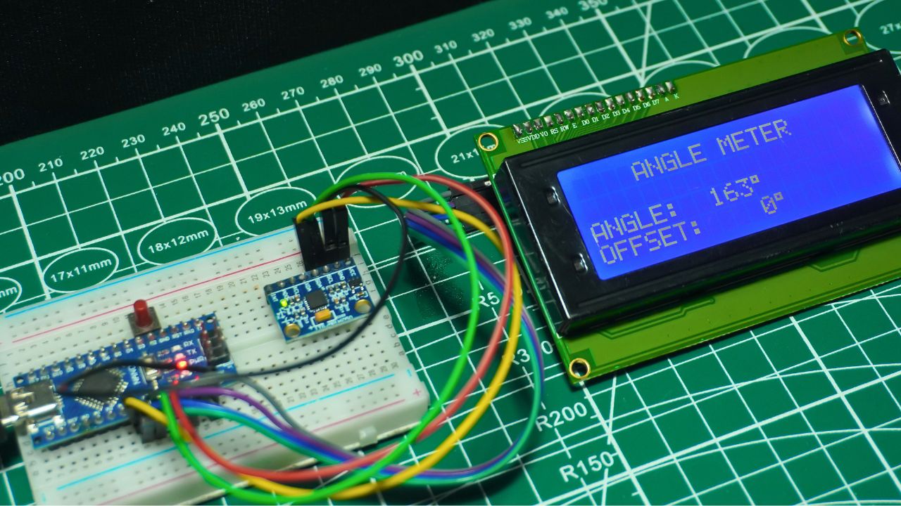
Imagine holding a small device in your hand that instantly tells you how much an object is tilted—just like the professional inclinometers used in engineering and robotics. With a few affordable components and some coding, you can create your own Arduino angle meter using MPU6050 and 20×4 I2C LCD display. This DIY project is not only practical but also an exciting way to learn about motion sensors, orientation tracking, and real-time data visualization.
At the heart of this build is the MPU6050 sensor, a powerful combination of accelerometer and gyroscope. While the accelerometer detects gravity to measure static tilt, the gyroscope tracks angular velocity for smooth motion detection. By combining both with a simple sensor fusion technique, you can achieve accurate and stable angle readings. The 20×4 I2C LCD display makes it easy to view roll and pitch data, calibration status, and even custom messages with plenty of space compared to a standard 16×2 LCD.
This guide takes you step by step through the working principle, wiring, Arduino code, and troubleshooting tips. Whether you’re a student, hobbyist, or robotics enthusiast, you’ll end up with a reliable DIY Arduino inclinometer project that’s both educational and fun.
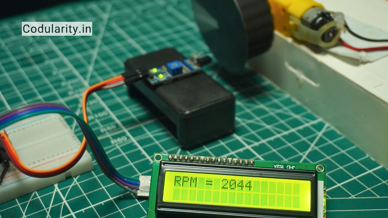
👉 If you’re interested in measuring motor speed, check out our complete guide on Digital Tachometer Using Arduino and IR Sensor, which explains step-by-step circuit, code, and working principle.
Project Overview

What is an Arduino Angle Meter?
An Arduino angle meter is a device that measures inclination angles (roll, pitch, sometimes yaw) using sensors and displays them. In this project, we use the MPU6050 sensor (gyroscope + accelerometer) to detect tilt, and a 20×4 I2C LCD display to show the angles in real-time. Key benefits include portability, affordability, and customization.
Why Use MPU6050 and 20×4 I2C LCD Display?
- MPU6050 offers 6 degrees of freedom: accelerometer gives static orientation (gravity vector), gyroscope gives angular velocity, which combined via filters or DMP (Digital Motion Processor) helps reduce drift.
- 20×4 I2C LCD display gives more lines than common 16×2, useful for showing both roll & pitch, calibration status, temperature, etc., while I2C reduces number of wires and complexity.
- Using I2C also helps in projects where wiring, power and space are constrained (e.g. on mobile rigs).
Circuit Schematic

Components Required
- Arduino Nano
- MPU6050 Sensor Module
- 20×4 I2C LCD display
- I2C Display Module
- Connection Wire
- 5v Power Supply
- Breadboard
Understanding Components
MPU6050 – Accelerometer & Gyroscope
Accelerometer – Measuring Gravity on X, Y, Z Axes
The accelerometer inside the MPU6050 measures the force of gravity across its X, Y, and Z axes. By analyzing these values, you can calculate the tilt of the sensor relative to the Earth. For example, when the sensor is perfectly flat, most of the gravitational pull is on the Z-axis. By applying trigonometric formulas like atan2, you can derive roll and pitch angles:
This gives a stable static orientation but can be noisy when the device is moving.
Gyroscope – Measuring Angular Velocity
The gyroscope measures angular velocity (degrees per second) around the X, Y, and Z axes. By integrating this data over time, the Arduino can track how much the device has rotated. Gyro data is smooth and responsive for dynamic movements, but it suffers from drift—small errors accumulate, making long-term readings inaccurate.
Sensor Fusion – Combining Accelerometer & Gyroscope
To overcome the weaknesses of both sensors, we use sensor fusion techniques like the complementary filter or the MPU6050’s built-in Digital Motion Processor (DMP). The filter blends accelerometer data (long-term stability) with gyroscope data (short-term responsiveness), giving accurate and stable angle readings. This balance makes the MPU6050 ideal for building a DIY Arduino inclinometer or angle meter.
For detailed technical documentation on the MPU6050 sensor, you can refer to the MPU6050 Accelerometer and Gyroscope Sensor Guide.
I2C Interface of LCD Display
The I2C (Inter-Integrated Circuit) interface is a widely used two-wire communication protocol that allows microcontrollers like Arduino to talk with multiple devices over the same bus using only two pins.
- SDA (Serial Data Line): Carries data between devices.
- SCL (Serial Clock Line): Provides timing signal that synchronizes communication.
To ensure reliable communication, the I2C bus requires pull-up resistors (typically 4.7kΩ–10kΩ) on both SDA and SCL lines. Many I2C LCD backpack modules already have these resistors soldered in, so you often don’t need to add external ones.
Typical I2C Addresses for LCD Modules
Most 20×4 I2C LCD displays use the PCF8574 I/O expander chip, which commonly has addresses 0x27 or 0x3F. If your LCD doesn’t respond, you can run an I2C scanner sketch to detect the correct address before initializing it in your Arduino code.
Wiring Schematic (Arduino Nano Example)
- LCD VCC → Arduino 5V
- LCD GND → Arduino GND
- LCD SDA → Arduino A4
- LCD SCL → Arduino A5
Source Code
#include <Wire.h>
#include <LiquidCrystal_I2C.h>
#include <MPU6050_light.h>

MPU6050 mpu(Wire);
LiquidCrystal_I2C lcd(0x27, 20, 4);

const int buttonPin = 3;
float angleOffset = 0;
bool buttonState = false;
bool lastButtonState = false;
float smoothedAngle = 0;
float alpha = 0.1;
unsigned long lastUpdateTime = 0;
const unsigned long updateInterval = 300; // ms

void showIntroScreen() {
  lcd.clear();
  const char* line1 = "ANGLE METER";
  lcd.setCursor((20 - strlen(line1)) / 2, 0);
  lcd.print(line1);

  const char* line2 = "MADE BY";
  lcd.setCursor((20 - strlen(line2)) / 2, 1);
  lcd.print(line2);

  const char* line3 = "CODULARITY";
  lcd.setCursor((20 - strlen(line3)) / 2, 2);
  lcd.print(line3);

  delay(2000);
  lcd.clear();
}

void setup() {
  pinMode(buttonPin, INPUT_PULLUP);
  Wire.begin();
  Serial.begin(9600);
  lcd.init();
  lcd.backlight();

  showIntroScreen();

  const char* initMsg = "Initializing...";
  lcd.setCursor((20 - strlen(initMsg)) / 2, 1);
  lcd.print(initMsg);

  mpu.begin();
  delay(1000);
  mpu.calcOffsets(true, true);

  lcd.clear();
  const char* readyMsg = "MPU6050 READY";
  lcd.setCursor((20 - strlen(readyMsg)) / 2, 1);
  lcd.print(readyMsg);

  delay(1000);
  lcd.clear();

  lcd.setCursor(4, 0);
  lcd.print("ANGLE METER");

  lcd.setCursor(0, 2);
  lcd.print("ANGLE: ");

  lcd.setCursor(0, 3);
  lcd.print("OFFSET:");

  smoothedAngle = 0;
}

void loop() {
  mpu.update();
  buttonState = (digitalRead(buttonPin) == LOW);
  if (buttonState && !lastButtonState) {
    angleOffset = mpu.getAngleX();
  }
  lastButtonState = buttonState;

  float rawAngle = mpu.getAngleX() - angleOffset;
  smoothedAngle = alpha * rawAngle + (1 - alpha) * smoothedAngle;

  unsigned long currentTime = millis();
  if (currentTime - lastUpdateTime >= updateInterval) {
    lastUpdateTime = currentTime;

    lcd.setCursor(7, 2);
    char angleStr[8];
    snprintf(angleStr, sizeof(angleStr), "%4d%c ", (int)smoothedAngle, 223);
    lcd.print(angleStr);

    lcd.setCursor(8, 3);
    char offsetStr[8];
    snprintf(offsetStr, sizeof(offsetStr), "%4d%c ", (int)angleOffset, 223);
    lcd.print(offsetStr);
  }
}Working Principle of Arduino Angle Meter
How Angle Is Calculated (Roll & Pitch)
The MPU6050 sensor provides raw accelerometer (X, Y, Z) and gyroscope (angular velocity) data. To convert this into tilt angles (roll and pitch), mathematical formulas are applied.
Using Accelerometer Data
The accelerometer measures the gravity vector, which can be used to determine the orientation of the sensor.
- Roll (rotation around X-axis):
- Pitch (rotation around Y-axis):
This method works well when the device is stationary, but accelerometer readings can be noisy in motion.
Using Gyroscope Data
The gyroscope measures angular velocity (°/s). By integrating angular velocity over time:
where ω is angular velocity and Δt is the time step.
Gyroscope readings respond quickly but drift over time, meaning errors accumulate if used alone.
Sensor Fusion, Filter Types & Calibration
To get accurate roll and pitch, sensor fusion combines accelerometer and gyroscope data.
- Complementary Filter:
A simple weighted average approach. Example:
Lightweight, works well for most Arduino projects.
- Kalman Filter:
More advanced filter that mathematically optimizes noise reduction and drift correction. It provides smoother angles but requires more computation. - Digital Motion Processor (DMP):
The MPU6050 has a built-in DMP that handles sensor fusion internally. With the i2cdevlib library, you can directly read quaternion or Euler angle values, reducing CPU load on Arduino. - Calibration:
Before using the sensor:
- Keep it level.
- Record offsets for accelerometer and gyro.
- Apply correction factors in code.
Calibration minimizes bias and ensures long-term accuracy.
Troubleshoot & Common Issues
Noisy or Unstable Angle Readings
If your Arduino angle meter with MPU6050 shows shaky or jumping values:
- Ensure a stable 5V power supply. Voltage drops or USB noise can cause inconsistent sensor output.
- Add decoupling capacitors (e.g., 0.1µF ceramic near the MPU6050 VCC and GND) to filter out power noise.
- Apply software filtering (low-pass filter, complementary filter) to smooth out sudden spikes.
- Use mechanical stability: mount the MPU6050 on a rigid frame, away from vibration sources.
Drift Over Time
A common issue is gyro drift, where angles slowly shift even when the sensor is still. To fix this:
- Use the accelerometer input or DMP (Digital Motion Processor) to correct gyroscope drift.
- Run a startup calibration: record offsets when the sensor is flat and subtract them from live data.
- Re-zero the system occasionally if absolute reference angles are needed.
LCD Display Issues
If your 20×4 I2C LCD display shows nothing or random characters:
- Check the I2C address. Use an Arduino I2C scanner sketch to confirm whether it is
0x27or0x3F. - Adjust the contrast potentiometer on the LCD’s I2C backpack to make characters visible.
- Verify all connections: SDA → A4, SCL → A5 (on Arduino Uno/Nano), plus correct VCC and GND wiring.
FAQ (Frequently Asked Questions)
Q1: Can this angle meter measure yaw?
Not accurately with just MPU6050. MPU6050 lacks magnetometer, so yaw (compass direction) will drift without external reference. To measure yaw properly, add a magnetometer (e.g. MPU-9250 or external sensor), or use DMP + external reference.
Q2: How precise is the roll and pitch measurement?
Depends on calibration, filtering, sensor quality. After proper calibration and using a complementary filter, error can be within ±1-2 degrees for static tilt. Dynamic motion can introduce momentary errors.
Q3: What is the working voltage of MPU6050 and I2C LCD?
Typically 3.3 V or 5 V tolerant (sensor often 3.3V logic but many breakout boards include regulator). The I2C LCD usually works at 5 V. Always check module specifications.
Q4: Which filter to use: complementary vs Kalman vs DMP?
Complementary filter: simple, low overhead.
Kalman: better performance but more computation, may be overkill for simple angle meter.
DMP: uses hardware of MPU6050 to compute fused output, best where library support and interrupt pins are available.
Summary & Final Thoughts
In summary, building an Arduino angle meter using the MPU6050 sensor and a 20×4 I2C LCD display is a practical and reliable way to measure tilt and inclination. This project demonstrates how an accelerometer and gyroscope work together to calculate roll and pitch angles, and how sensor fusion techniques like the complementary filter or Digital Motion Processor (DMP) reduce drift and noise.
To ensure accurate results, focus on:
- Correct wiring and stable power supply.
- Proper calibration of both accelerometer and gyroscope.
- Using filters to minimize drift and vibrations.
- Troubleshooting common issues such as LCD I2C address errors or noisy sensor outputs.
This project is not only a great DIY electronics tutorial but also has real-world applications in robotics, level detection, educational tools, and remote monitoring systems. With the complete working principle, step-by-step code, and troubleshooting tips provided above, you now have the knowledge to build a robust and high-accuracy Arduino angle meter that’s both cost-effective and customizable.